
The GSM Association (“Association”) makes no representation, warranty or undertaking (express or implied) with respect to and does not accept any responsibility for, and hereby disclaims liability for the accuracy or completeness or timeliness of the information contained in this document.
Executive Summary
Turkcell’s case study focuses on holistic infrastructure management for Direct Current (DC) power systems, acclimatisation and generators, which was developed largely in-house. The solution is focussed on two key innovations; Intelligent infrastructure, enabled through the transformation of legacy equipment with cost-effective solutions and sensors developed in house by Turkcell and; Hardware investment and deployment based on actual site needs to provide remote management capabilities.
Following site deployments, tailor-made and future-proof software platform solutions were created with local infrastructure management partners. The following capabilities making remote infrastructure monitoring and management possible have been identified and produced:
- Information about site power infrastructure and environmental conditions
- Automatic corrective actions by the management system to increase energy and operational efficiency
- Reports about infrastructure power capacity utilization, temperature distribution and battery performance.
Using the information gathered and reports compiled by infrastructure management platforms, investment decisions became more informed, precise temperature management was achieved, and power system and battery dimensioning strategies were created. Excess hardware that was installed on sites was removed and re-utilized, technical requirements for new purchases were reshaped and generator fuel consumption was optimized.
As networks evolve through 4.5G to 5G and continue to become more complex, some industry forecasts are predicting a 2 to3-fold increase in energy consumption. It is therefore critical that powering the networks of the future remains economically viable.
About Turkcell
Turkcell is a digital operator headquartered in Turkey, serving its customers with its unique portfolio of digital services along with voice, messaging, data and IPTV services on its mobile and fixed networks. Turkcell Group companies operate in 8 countries – Turkey, Ukraine, Belarus, Northern Cyprus, Germany, Azerbaijan, Kazakhstan, and Moldova. Turkcell launched LTE services in its home country on April 1st, 2016, employing LTE-Advanced and 3 carrier aggregation technologies in 81 cities. In 2G and 3G, Turkcell’s population coverage in Turkey is at 99.59% and 97.98%, respectively, as of June 2018. Turkcell offers up to 10 Gbps fibre internet speed with its fibre to the home (FTTH) services. Turkcell Group reported TRY5.1 billion revenue in Q218 with total assets of TRY41.0 billion as of June 30, 2018. It has been listed on the NYSE and the BIST since July 2000 and is the only NYSE-listed company in Turkey.
Read more at www.turkcell.com.tr
Introduction
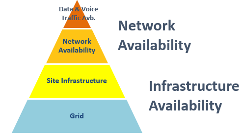
Mobile Network Operators target to offer 99.999% network availability to their subscribers so that they can enjoy a high quality, and uninterrupted service. As Figure 1 shows, achieving this objective requires the support of the underlying layers and therefore it requires the ability to manage and coordinate the network elements.
 | 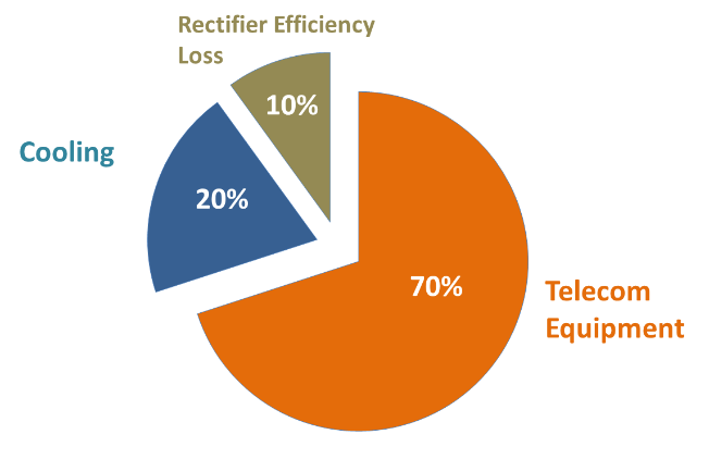 |
| Figure 1: Hierarchical view of high availability network | Figure 2: Breakdown of main cost lines for a site |
As a highly available network may prove expensive, it is vital for operators to adopt energy efficiency solutions and ensure that the network can be built and managed in the most cost-efficient manner especially at the infrastructure layer that attracts a large proportion of the operator’s costs (see Figure 2).
This case study focuses on both the challenges faced and the optimisation delivered by Turkcell in their network transformation projects.
Intelligent infrastructure
While typically telecommunications core networks enjoy the benefits of having well-established management systems (including remote management systems), the critical elements for site infrastructure such as power systems, batteries, air conditioners, free cooling and generators (gen-sets) often do not come with holistic, well-developed management systems.
Deploying remote monitoring and management functions for the main site infrastructure elements allow operators to identify CAPEX and OPEX reduction opportunities and develop energy efficiency strategies. We refer to this new breed of infrastructure as “intelligent infrastructure”.
Bespoke solutions based on requirements
In Turkcell’s case, infrastructure equipment either lacked remote connectivity or had limited support for remote management, with no well-established management system that supported all of the requisite infrastructure equipment.
In conventional management system deployments, an intelligent site controller connects to various site infrastructure equipment using standard communication protocols such as RS232, RS485, and CANBUS. A site controller is required regardless of specific site features (infrastructure equipment combinations, number of power systems presence of stationary gen-set, and so on).
It is clear that this type of deployment is not cost-effective for remote infrastructure management as it requires significant investment for the intelligent site controller, complex installation work per site and may often result in overprovisioning of capabilities.
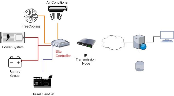 | 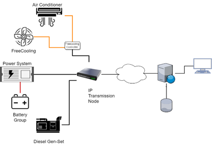 |
| Figure 1a. Conventional Site Infrastructure Management | Figure 3b. IP Enabled Infrastructure Devices |
Turkcell designed its own solution based on their specific equipment types and site requirements. Following a detailed analysis of power systems, air conditioners and gen-sets and other equipment Turkcell selected an IP-based communication interface in order to add remote management capabilities and to connect to separate infrastructure equipment.
Intelligent IP-based Power System Upgrade
For Turkcell’s power systems, the only available communication interfaces were RS232 or USB ports, which required the installation of special PC software or simple dry contact alarms.
In order to add the remote management capability, SNMP & IP remote access cards were installed to the power system controllers which were manufactured by the original power system manufacturer.
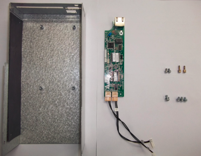 |  |
| Figure 4a. SNMP & IP remote cards in the existing casing to enable upgraded functionality | Figure 4b. the upgraded case with SNMP remote card and USB connectivity. |
Since 2010, Turkcell has updated its Power System Technical Requirements Documentation and SNMP & IP remote access functionality for all power system controllers was made mandatory in all new purchases.
Turkcell upgraded their existing power infrastructure for around 50% of its base station sites with SNMP&IP remote access cards which were deployed over a 4-year period. Hardware and installation costs vary depending on operator conditions, can be approximated between $250 USD – $350 USD. However, the initial firmware running on SNMP&IP remote access cards provided limited functionality, only supporting a simple web interface for system monitoring and SNMP alarm signalling.
Turkcell’s infrastructure management requirements were more sophisticated and required additional standardised functionality from the manufacturers to be developed. This included a significant upgrade in connectivity metrics, however, limited remote management functionality (see appendix 2 for initial requirements).
Acclimatisation control modules
For air conditioner systems, free cooling solutions that utilised an air conditioner and a fan unit (depending on temperatures) were already deployed for energy efficiency. But remote management functions for algorithm changes and measurement of temperatures were not available, meaning that the system worked based on an embedded algorithm which was set during production.
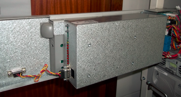
In order to meet Turkcell’s requirements and enable the full remote management capability, new controllers with IP remote access functions were designed and deployed by working closely with a local manufacturer. Hardware and installation costs vary depending on operator conditions, can be approximated between $100 USD – $200 USD. (see Appendix 3 for additional remote site upgrade requirements).
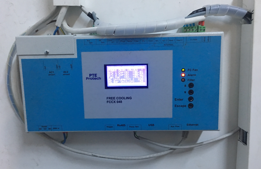
Figure 5. Upgraded remote management capability developed locally by Turkcell and third party.
In some instances, a more basic solution was required to measure internal site temperature alone. Simple and cost-effective IP based thermostats were developed and deployed in conjunction with local manufacturers. Hardware and installation costs can be approximated between $50 USD – $100 USD.
Turkcell deployed free cooling control module with remote management capabilities to around 20% of its base station sites and thermostat units with remote management capabilities to around 10% of its base station sites.
Generator control cards
Turkcell also made significant improvements to gen-set equipment by upgrading control cards. With this investment, functions such as manual start-stop, test mode, automatic mode, changing of start-stop conditions and measurements of AC phase voltages, gen-set AC output phase voltages, fuel level, oil level, oil temperature, oil pressure, engine speed, frequency, load currents, and runtime were made possible to manage remotely.
Control cards had already been deployed for stationary gen-sets which enabled gen-set start and stop functions. However, because half of the gen-sets in the network only supported point-to-point connection via sim-cards, the system was unable to connect or provide management for more than one gen-set simultaneously and therefore was not cost-effective due to the high communication costs when using GPRS.
In 2013, a local brand gen-set control card was selected to provide remote management functions for algorithm changes, measurement of gen-set values and manual start-stop function. This card was supported by Ethernet or GPRS interface and could be utilised for the whole network. All new generators are being purchased with this control card as standard.
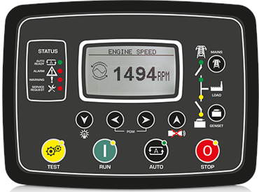
| Figure 6. Generator control module connection interfaces, supporting Ethernet and GPRS Connection Options |
For older gen-set control cards that had been purchased previously, remote management capabilities were installed via an interconnection module to meet Turkcell’s requirements. Thus, all the stationary generators in the network are now controlled remotely.
Hardware and installation costs vary depending on operator conditions, can be approximated between $250 USD – $350 USD.
Around 10% of Turkcell base station sites have stationary generators and all these generators gained remote management capability over the course of a 2-year period.
Management system software deployment
For many infrastructure equipment deployments, remote management has two main problems. Firstly, as the number of devices to monitor increases, manual operations become impractical. To overcome this issue it is important to develop an interface compatible with all devices.
Secondly, the remote management system needs to be sufficiently flexible to support multiple variants of equipment produced by different manufacturers. For example in the Turkcell case, there were three different rectifier brands, two different free cooling brands, three different generator control modules and so on. In order to overcome this problem, new management software was designed and implemented for each infrastructure product. This was written by local companies in Turkey resulting in lower cost and tailor-made solutions to be developed.
Economic effects of remote management
CAPEX
Rectifier capacity dimensioning
Rectifier capacity utilization reports highlight where standard power system capacity is over-dimensioned compared to actual needs.
In the graph below the standard power system capacity was 12kW for new purchases. After evaluating actual loads and power system utilisation, power system capacity was re-dimensioned to 9kW by reducing the number of modules from four to three. This resulted in around 20% capex saving for each power system investment.

Figure 7. Capacity utilization distribution
Removing excess power system capacity
Identifying where excess power exists allows for the redeployment of power capacity to sites where it is needed more. The rectifier capacity utilization report provides information about the average load per power system and advises how many modules are needed. If the power system has excess capacity, modules are able to be removed.
By collecting 7% of existing rectifier modules and re-utilising them at new sites rather than investing in new modules, Turkcell was able to identify a significant CAPEX saving.
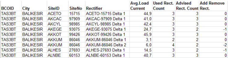
Figure 8. Site-based rectifier module removal advice report
Battery dimensioning strategy
By gathering information about DC power consumption and grid cut-off statistics per site via remote management systems, a precise method to dimension battery backup time and a number of batteries per site can be developed. Instead of standard battery backup duration targets, backup time requirements based on actual availability targets and grid cut-off statistics for each site are calculated.
The number of battery sets to achieve the necessary backup time for a specific site can be calculated by measuring specific DC power consumption per site based on the following metrics:
Total DC consumption x Necessary backup duration -> Number of battery sets
By applying this battery dimensioning strategy for the whole network, the number of batteries necessary to achieve availability targets can be calculated. The automated remote battery test can indicate necessary battery replacement, as well as detect potential battery faults that can lead to degraded backup duration.
As an example, after completing battery dimensioning on all sites, the actual number of batteries in the network was reduced by 20%.
OPEX
OPEX is a critical factor in determining financial success for an operator and therefore much importance is placed on reducing costs, in particular, energy costs.
According to Capgemini’s report “Operational Cost Strategies for Mobile Operators in Europe” released in 2009, energy costs are more than 20% of all OPEX costs for a Telecom operator.
With the help of more efficient management systems, energy OPEX can be reduced in a number of ways.
Energy Efficiency Features of Radio Equipment
The majority of overall energy consumption in a base station site comes from Telecom equipment generating and amplifying radio signals. In order to reduce the power consumption of this equipment, vendors offer many different solutions and features. Some of the energy efficiency features of radio equipment are listed below:
- Multi-Carrier Intelligent Voltage Regulation
- Dynamic TRX Working Voltage Adjustment
- Multi-Carrier Switch off Based on Traffic Load
- Power Optimization in Broadcast Frequency
- Multi-Carrier Switch off Based on Quality of Service
- Mains Triggered TRX Shutdown
However, implementing all of these features can be expensive for the operator and it is important to measure the actual benefits of the features to decide whether to invest or not.
Collection of load data from the majority of rectifiers across the Turkcell network has greatly simplified the process of assessing the impacts of an action (or a power saving feature). The graphs below show the effects of two different power saving features. It is immediately obvious that while the first feature generated a significant reduction in overall site consumption, the effects of the second feature was negligible.
By activating the most suitable features for the Turkcell network configuration, it was possible to produce annual savings in the order of 20M kWh, significantly reducing the network OPEX.
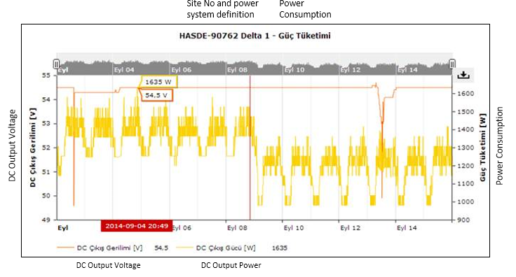
Figure 10. Energy saving measurement of sample radio network feature
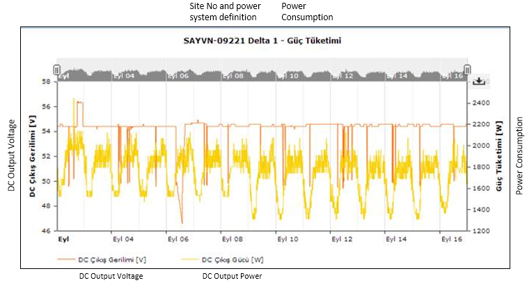
Figure 11. Energy saving measurement of sample radio network feature
Modernization
Modernisation of the radio equipment, the main responsible for electricity consumption in mobile networks has produced significant savings. On average, Turkcell observed a reduction of 20% in energy consumption keeping the same radio capacity just through a programme of base station equipment modernization.
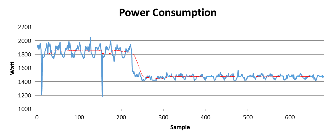
Figure 12. Modernization effect on power consumption
Most of the base station cabinet’s power consumption is drawn by the power amplifier. Efficiency can be increased with different amplifier types or signal processing techniques. Maximum efficiency increases can be achieved by installing newer radio equipment and removing legacy cabinets from the network.
It should be noted that since modernization requires a major CAPEX outlay in terms of equipment and additional installation cost, modernization alone will not achieve significant gains in energy efficiency. An operator should also consider the additional motivation of better signal quality, increased coverage, and capacity for a modernization project.
Module efficiency increase
All power modules in rectifiers have an efficiency curve similar to the graph below. The efficiency of the rectifier module is highly dependent on the load. At low loads per module, the rectifier efficiency drops, therefore more energy is dissipated to heat. In order to reduce the energy consumption of the site, the efficiency should be increased.
There are a number of ways to achieve this. One way is to use rectifier modules with higher efficiencies. This achieved by moving from the blue efficiency line to green efficiency line as shown in the graph. By switching to a more efficient module, losses on the rectifier modules could be reduced.
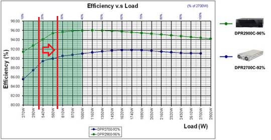
Figure 13. Rectifier efficiency vs load
The efficiency of rectifier modules has increased from 92%-96% since the early part of the 21st century. However as efficiency increases, so does the price. At present, rectifier investment is costly and therefore it is not realistic to replace current rectifier modules with more efficient ones just to see a reduction in OPEX.
Turkcell’s innovative solution was to make the current rectifier modules work with higher loads in order to reduce losses. As can be seen in the above graph, when the load on the rectifier module increases, so does the efficiency. Rectifier modules share the load equally, so when one or two modules are removed from the rectifier cabinet, the remaining modules are required to generate more current, thereby increasing their load.
In order to determine the rectifier units that could be removed, we used the capacity utilisation report. The below graph shows the capacity utilisation of all rectifiers in the network when the rectifier management system was initially launched. More than 50% of the rectifier modules were working at less than 20% cent of their capacity.
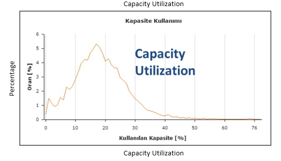
Figure 14. Rectifier capacity utilization distribution
Trials were conducted at a sample of base station sites and one of two rectifier modules were removed depending on the load and battery capacity on the sites. The results can be seen below.
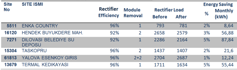
Figure 15 Module removal effect
On average, an energy saving of approximately 2.5% was measured across all sites. The overall energy saving across the network varied depending on the module efficiencies used and how capacity was utilised depending on the loads. In this case, around 7% of all rectifier modules in the network were removed from rectifier cabinets, generating an OPEX energy saving of approximately 3GWh annually.
Rectifier power saving features
As previously mentioned, to reduce losses on the rectifier modules, increases in the efficiency of the rectifier module was necessary. Module reduction did achieve this outcome, however, it is necessary to have some excess capacity in rectifier cabinets for two reasons;
- To charge batteries after a grid failure. Batteries must be charged with suitable currents and Telecom equipment at the site must be fed simultaneously.
- For redundancy. If one of the rectifier modules fails, the remaining ones can keep generating the necessary current. Additionally, since all rectifier modules work with a different AC phase, additional modules are required for AC phase redundancy.
When considering these constraints on removing excess rectifier modules, another way to increase the efficiency of each module was required. Turkcell implemented energy efficient algorithms that showed the rectifier control module monitoring the necessary current for the load and putting the excess modules into standby mode. The logic behind this feature can be seen in the below visuals. Rectifier modules work with load sharing, therefore when one of the rectifier modules is in standby mode, other active modules generate more current and are able to work at a more efficient rate.
Using a rectifier management system, this feature can be activated remotely, thereby eliminating the need for site visits.
When the power saving algorithm was activated on all rectifiers in the network, a more than 2% decrease was measured in the overall site energy consumption, generating more than 30M kWh in energy savings annually from the OPEX expenses of the network.
The below graphs show the change in the energy consumption of sites after the power saving algorithm has been applied. The green box shows when the algorithm is activated. The red lines in the graphs represent air conditioning energy consumptions. The blue lines represent the Telecom equipment energy consumption and the yellow lines represent the overall consumption of the sites.
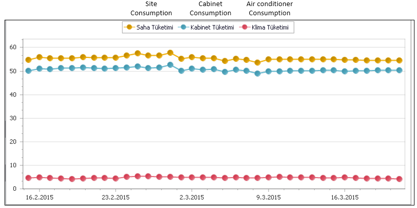
Figure 16. Energy saving measurement after activation of rectifier energy saving features
Converter removals
Further to the rectifier modules in a base station site, there are also converter units which convert the -48VDC to +24VDC voltage level.
The purpose of converter units is mainly due to old Telecom cabinets requiring +24VDC voltage as input. Most of these types of cabinets have been replaced over the years in Turkcell’s network, however, some of the converter modules, required for feeding the equipment were not removed.
The deployment of the rectifier management system made it possible to detect a number of base station sites where redundant converters existed. These converter units consumed a small amount of residual electricity and therefore it was decided to uninstall them from the network.
Excess converter modules were removed from all rectifiers in the network and this generated more than 500,000 kWh energy savings annually.
Invoice controls
When considering the number of base stations in a network, it is important to control the energy consumption bills for each site. Before deploying the rectifier management system, there was no option to compare and contrast data from different base station sites or bills over a period of time.
With the rectifier management system, the DC load in every base station site can be measured enabling the power consumption from the grid to be calculated accordingly. By adding the cooling consumption, an estimated energy consumption can be compared against the energy bill. This data enables payments to be verified, minimizing inaccurate payments.
Generator start-up algorithm
A majority of telecom operators use some sort of backup power in their network. Most of the time backup power is covered by batteries, however, in addition, generators are used to increase the backup time. Prior to deploying the remote management system, during a grid outage, generators would start up within 15 minutes of the grid outage. The cost of starting the generator is considerably higher compared to covering the backup need with batteries.
For reducing the generator working hours and decreasing fuel costs, the algorithm below was designed. This algorithm monitors all AC phases, battery discharge status, battery voltage and internal temperature. Combining all these parameters, the generator is only started when it is absolutely necessary.
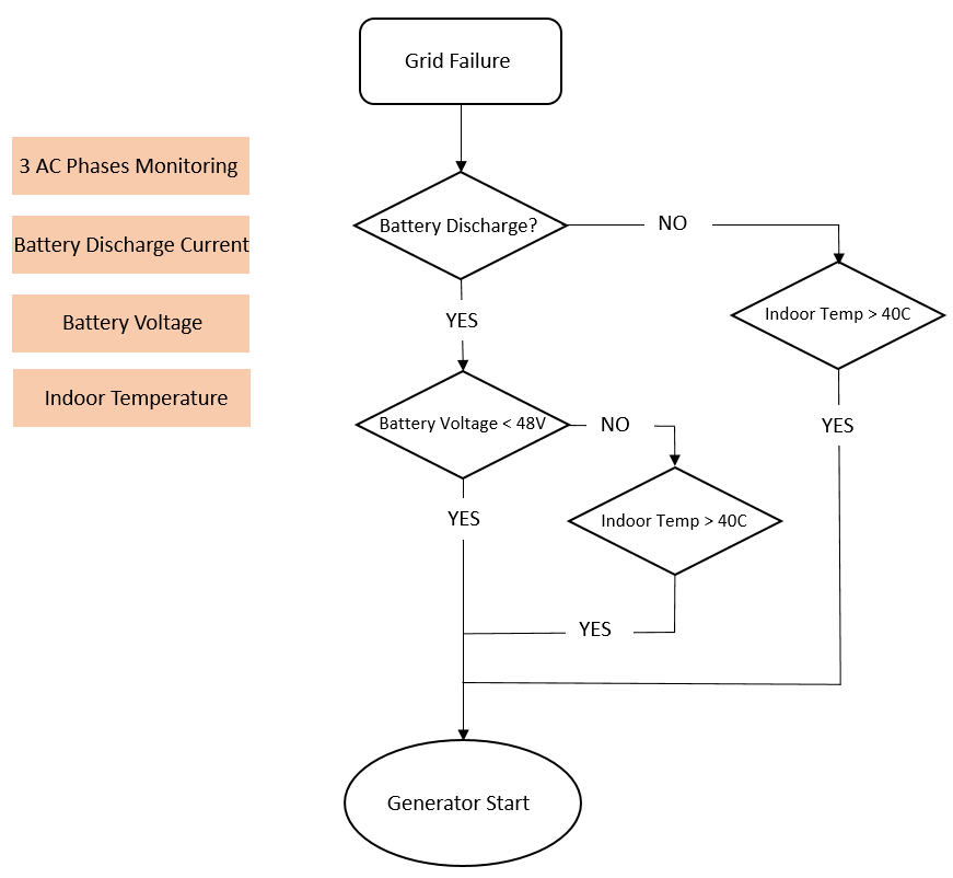
Figure 17. Grid failure process flow
After all 3 AC phases are restored, the generator stops with a short delay.
Increasing site temperature
Acclimatisation energy consumption is one of the main components of overall base station energy consumption. The amount of energy used for acclimatisation depends on many parameters, including the technology of the air conditioner (AC) unit (whether it is an inverter or on-off type), the set temperature of the AC, outdoor temperature and additional free cooling equipment.
The percentage of AC energy consumption from all site energy consumption changes depending on the factors above. In some base station sites, ACs consume around 8 % of total energy yet in other base station sites, AC energy consumption can be as high as 20 % of total energy consumption. In order to reduce energy consumption in a base station site, free air cooling units were deployed, (cool air from outside, brought inside with the help of a DC fan). The free air cooling units have the functionality to activate AC units if the indoor temperature increases.
During trials of the free cooling remote management system, the average temperature of base station sites was increased from 24°C to 30°C in all our base station sites. The result of this action was an energy saving from air conditioner energy consumption of more than 10M kWh annually.
However, one disadvantage of this temperature increase was the negative effect to the life expectancy of batteries. There is a negative relationship between battery temperature and battery life. The ideal working temperature for batteries is between 20°C and 25°C.
The negative effect on battery life can be combated by decreasing the base station average temperature and cool the site without using the air conditioner unit, maintaining the indoor temperature closer to suitable levels for batteries. This is practical when then the outdoor temperature is cold enough to cool the base station site, ideally during winter periods. Additionally, emergency cooling of free cooling units decreases the site temperature in cases of air conditioner failure, preventing batteries from excess temperatures.
Every 1°C increase in site temperature results in a 3% decrease in the lifetime of the battery. Using remote management for changing parameters, decreasing average site temperature in winter and emergency cooling positively increased the battery lifetime by more than 5%.
Conclusion
The in-house development of infrastructure by Turkcell to improve the monitoring and remote capabilities of base station equipment provides an easy method to improve site efficiency at relatively low cost with clear OpEX benefits. This has been achieved without the purchase of new equipment or on boarding of third-party vendors, though still requiring input and an additional benefit is that these have been specifically designed with Turkcell’s requirements in mind.
Appendix 1: Turkcell’s Infrastructure Management system capabilities
An efficient infrastructure management system must be able to provide users with summary reporting information for decision making, support automated functions and take corrective actions.
Reporting capabilities
The infrastructure management systems created by Turkcell provides a variety of reports to support decisions for CAPEX and OPEX reduction and energy efficiency.
Basic data log for power systems
By gathering periodical measurement data from power systems, site power infrastructure can be examined in detail and the results of changes made for energy efficiency can also be calculated.
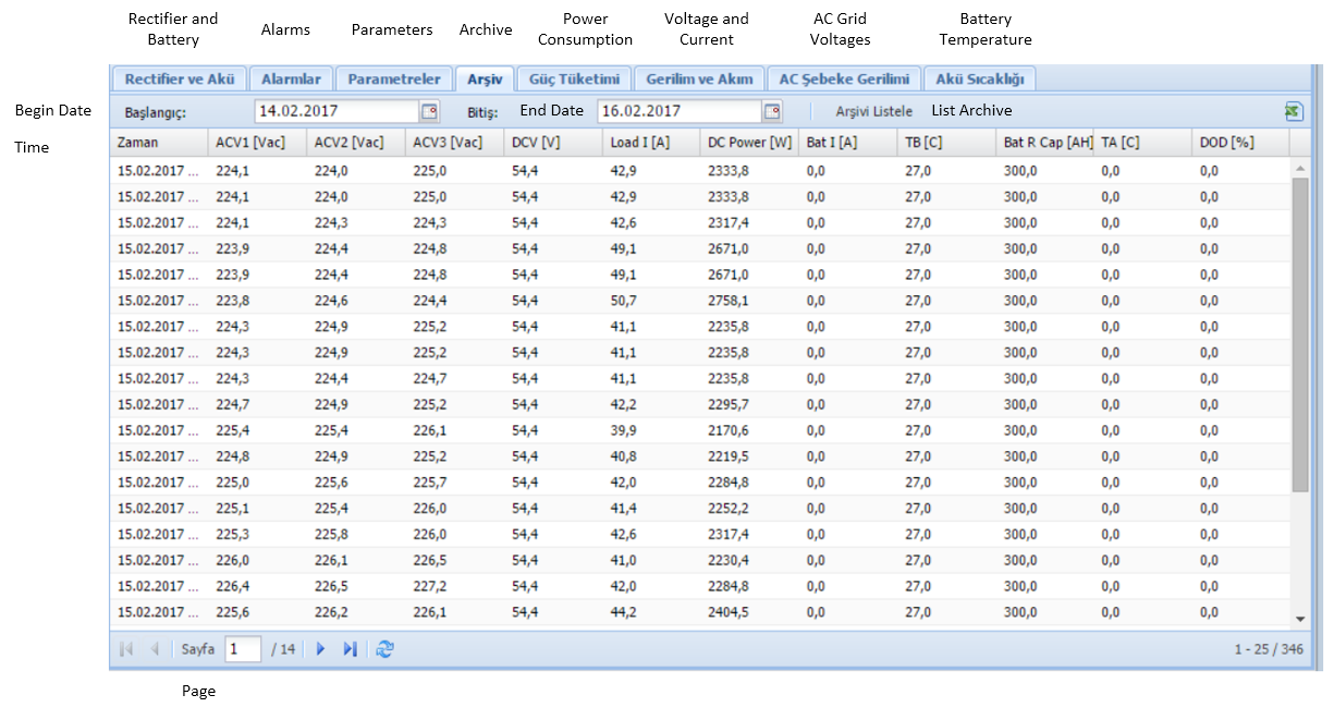
Figure 18. Basic data log
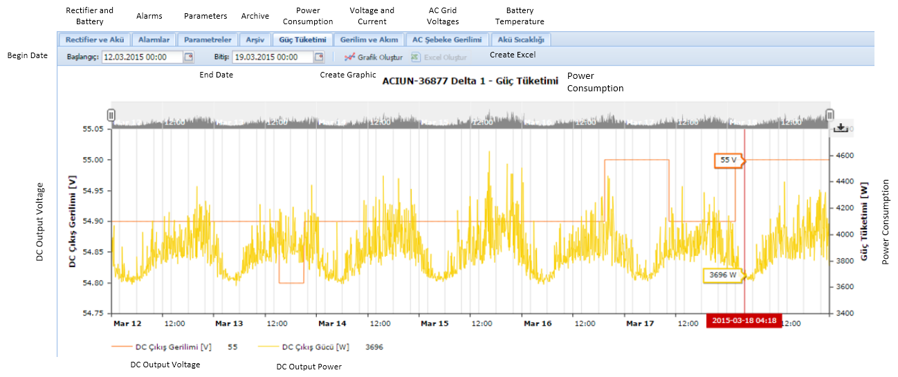
Figure 19. Archive and Power consumption graph
Power system capacity utilization
DC power system capacity utilization directly affects energy efficiency and with low-utilization, energy efficiency is reduced and OPEX costs increase and it is likely that the power system capacity is over-dimensioned.
With the power system capacity utilization report, capacity utilization is calculated per site, per region or for the whole network and power system capacity dimensioning can be done by evaluating results.
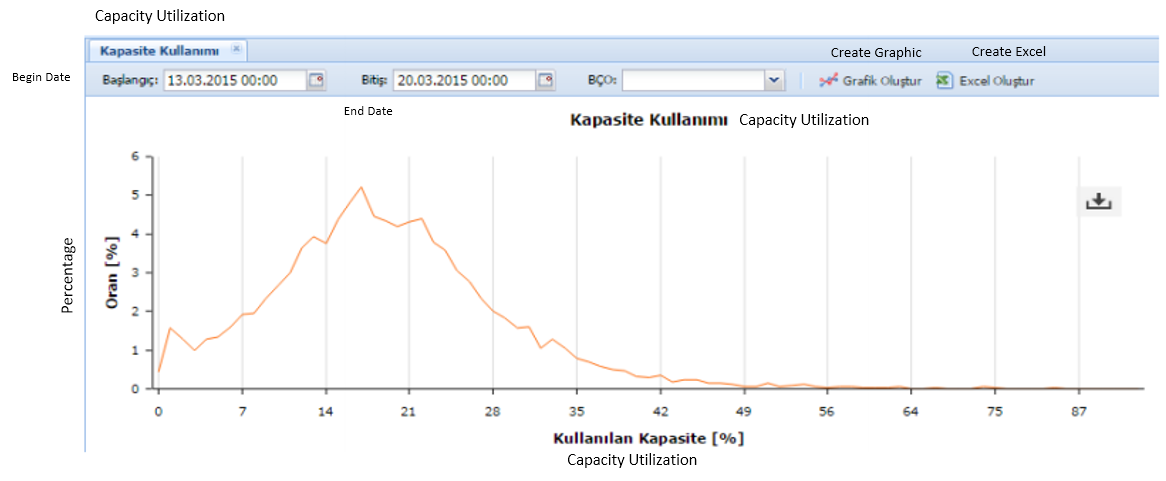
Figure 20. Capacity utilization distribution
Rectifier capacity reconfiguration report
Rectifier capacity utilization relates to the efficiency of the load per rectifier module, and at low loads per module (when part of the rectifier capacity is used) the rectifier efficiency is reduced and the energy consumption of the site is increased.
The following rectifier module efficiency graph shows load-dependent efficiency change.
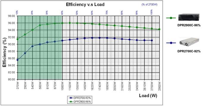
Figure 21. Rectifier efficiency versus load
In order to increase the capacity utilization of the rectifier module, it is necessary to reduce the number of rectifier modules and to increase the load per module. The following report details the average load per power system and advises how many modules are required. If the power system has excess capacity, modules should be removed.

Figure 22. Rectifier module number advisory report
In cases of insufficient power system capacity for redundancy purposes, module addition is advised.
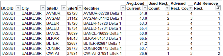
Figure 23. Rectifier module advisory report
Battery temperature report
For optimal battery life and energy efficiency, the site internal temperature is an important parameter. The below report shows information about temperature distribution for specified date range per site, per region or for the whole network.
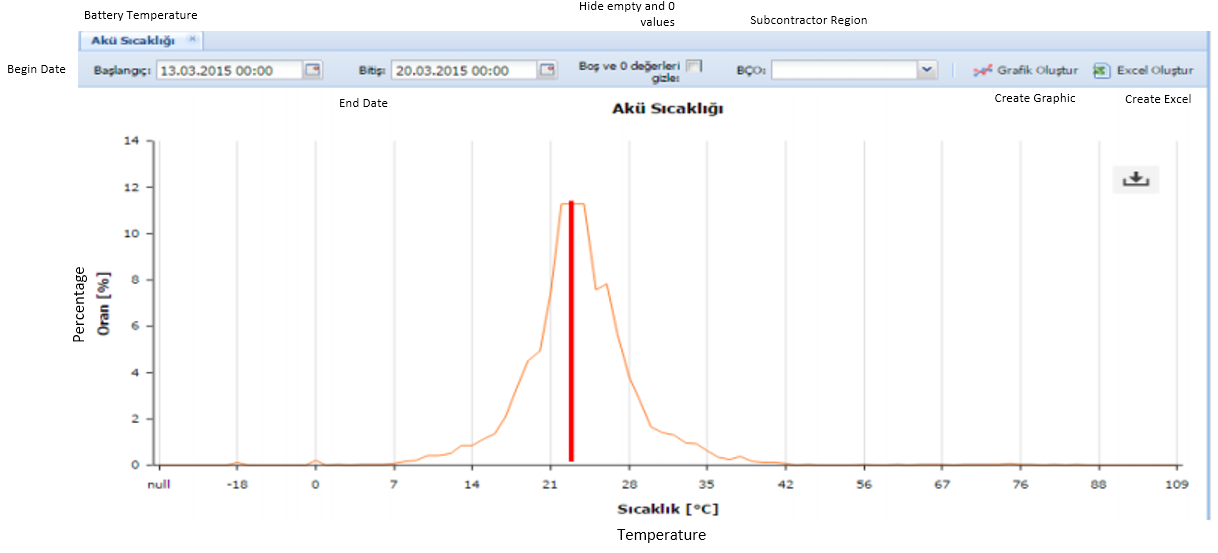
Figure 24. Battery temperature distribution
Temperature and humidity report
Utilising the free cooling management systems, each base station site’s indoor, outdoor temperatures, and humidity levels are collected and measured as displayed in the graph below. In base station sites where only a thermostat is installed only the indoor temperature can be monitored.
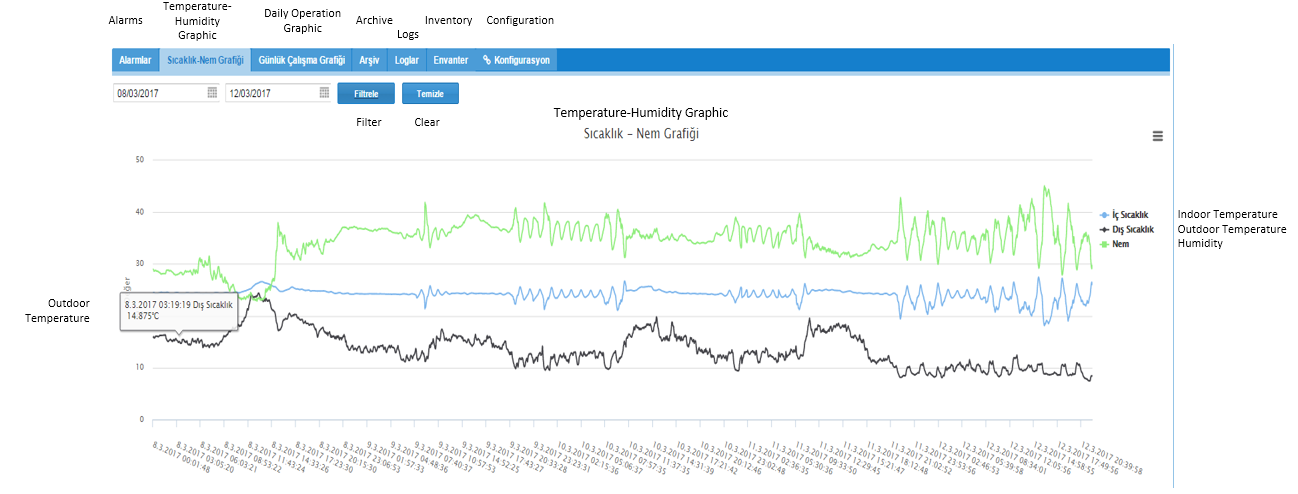
Figure 25. Indoor/Outdoor Temperature and Humidity levels
Automated Functions
The Management System created by Turkcell has automated functions that take corrective actions at the site infrastructure level for increased OPEX and CAPEX efficiency.
Site profiles and parameter sets
The rectifiers defined in the rectifier management system are controlled by various parameter sets according to the site type, the rectifier brand/model, and the battery type connected to the rectifier. New site profiles and or parameter sets can be added to the system, with power systems or sites automatically assigned to different profiles according to the location or inventory criteria.
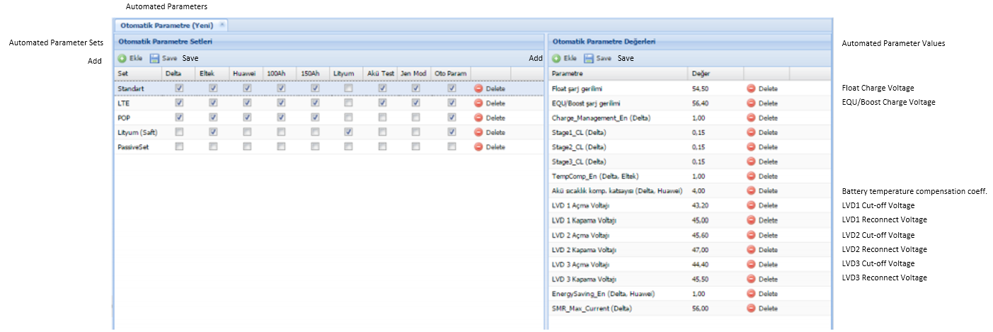
Figure 26. Parameter sets/translation
Parameters for power systems in the network can be easily managed, allowing energy-saving features at power system level to be turned on network-wide.

Figure 27. Network-wide parameter management
Remote battery tests
Network battery quality is a significant factor that impacts a network’s OPEX and CAPEX efficiency. By monitoring network battery quality, early detection can reduce the disruptive effect of a single faulty battery and therefore the corruption of the whole group can be prevented.
In a large network, it can be challenging to monitor network-wide battery quality and conditions. Turkcell’s rectifier management system has automated battery test functionality that tests battery capacity at each site without the need of user interaction. Tests are started by the central management system and managed by a rectifier controller. DC output voltage can be lowered to start battery discharge without power cut-off.
The test results are evaluated automatically and sites with degraded battery capacity are reported. By evaluating battery test results, sites that require battery replacement can be detected and service failures avoided.
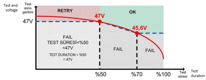
Figure 28. Battery test decision regions
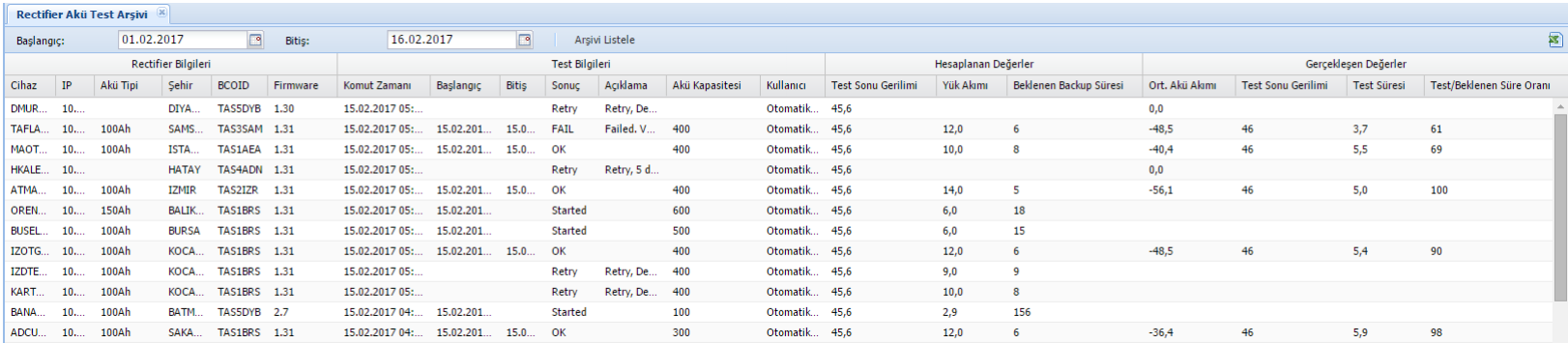
Figure 29. Periodical Battery Test Results
Real-time Monitoring for Operation
Operational decisions rely on accuracy and precision in order to achieve an OPEX efficient network and minimal service loss. With real-time monitoring remaining battery capacity can allow for the prioritization of network operations during grid cut-offs.
Real-time battery voltage is reported on the dashboards for sites that experience grid power loss.
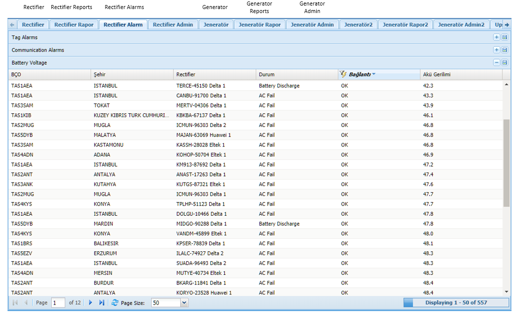
Figure 30. Real-time battery voltage monitoring
Appendix 2: Additional requirements from the SNMP upgrade
- An Ethernet interface that can provide TCP / IP connectivity on the power system controller.
- A web interface for management via TCP / IP connection.
- Communication support with SNMP protocol via TCP / IP. SNMP protocol MIB files for rectifiers will be provided by the manufacturer.
Metrics via the SNMP protocol on the rectifier to include:
AC phase voltages, DC output voltage, DC output current (load current), remaining battery capacity, battery depth of discharge, battery current battery temperature, ambient temperature, rectifier output current (for each rectifier), rectifier utilization rate, rectifier status(Float, EQU, Battery discharge etc.)
Modifiable Parameters by accessing the rectifier with the SNMP protocol.
Field name, field location, system description, float charge voltage, EQU / Boost charging voltage, charge current limit, battery capacity, rectifier control (each rectifier module can be turned on and off remotely), periodic battery test parameters, manual battery test parameters, LVD on and off voltage setting values, LVD control commands (each LVD can be turned on and off remotely), battery charge temperature compensation parameters, DC output voltage low alarm threshold value
SNMP alarms generated in the rectifier controller for alarms related to the following rectifier system including Rectifier alarms, LVD trip alarms, temperature alarms, sensor fault alarms, AC phase interrupt alarms, AC phase voltage alarms, battery and load fuse alarms, battery test failure alarms, rectifier overload alarms, DC output voltage high and low alarms, current limit overshoots
Rectifier controller should allow for the rectifier modules to be turned on and off programmatically, depending on the load, using energy efficiency algorithms.
Rectifier controller will allow periodic and manual battery tests to be done remotely on the power system. The systems will support the functions that will carry out the constant current load test.
Rectifier system should allow firmware updates via remote connection.
Rectifier system should allow IP address changes with a remote connection.
For air conditioner systems, free cooling solutions that utilised an air conditioner and a fan unit depending on inside and outside temperatures were already deployed for energy efficiency. But remote management functions for algorithm changes and measurement of temperatures were not available. The system worked based on an embedded algorithm set at production.
Appendix 3: Additional remote site requirements
- Monitoring and management of features below were standardised;
- Container inner temperature, outdoor temperature, internal humidity
- Fan power consumption, air conditioner electricity consumption
- Fan Type
- Air conditioning working temperature, air conditioning stop temperature
- Fan working temperature, fan stop temperature
- Inside-outside temperature difference, maximum internal temperature, internal humidity
- Air conditioning protection delay, emergency fan stopping temperature
- FC deactivated outdoor temperature
- Fan day speed, fan night speed
- Heater working temperature, heater stop temperature, heating method
- Night mode start time, night mode end time, night/day mode selection
- Maximum fan speed at a critical temperature
- Alarm set values, active/inactive information of alarms
- High-temperature alarm, low-temperature alarm, high humidity alarm
- Free cooling failure alarm, free cooling fan failure alarm, free cooling fan speed (rpm) alarm, free cooling fan consumption alarm, filter dirty alarm
- AC phase alarm (optional), DC battery voltage is high (optional), DC battery voltage is low (optional)